
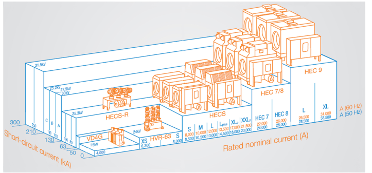
Large Generator Circuit Breakers are like no others. With ratings to match generators of 1000MW or more, they are massive devices with continuous current ratings in excess of 25,000A at voltages of the order of 24 - 36kV. Currents of this magnitude would be considered to be fault currents in any other environment.
Standards
Generator circuits experience conditions that are not common and are certainly more demanding than those experienced in normal distribution circuits. These unique characteristics require breakers that have been specifically designed and tested to demanding standards. Up till 2015 the only standard recognised worldwide to specifically addressing these requirements was IEEE C37.013.
Recently the IEEE joined forces with the IEC to produce the latest IEC/IEEE 62271-37-013 Standard, also called Dual Logo Standard which aims to define and regulate the circuit breakers used to protect generation assets.
Types of Faults
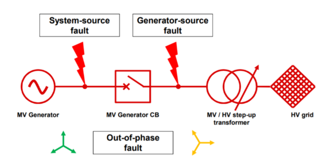
Three different types of fault which GCBs must be capable of clearing are as follows:
- Fault between the generator and the GCB, called system-source fed fault
- Fault between the GCB and the step-up transformer, called generator-source fed fault
- Out-of-phase fault (OOP)
Abbreviations
GCB – Generator Circuit Breaker
SLD – Single Line Diagram
SSF – System-source fed Fault
GSF – Generator-source fed Fault
OOP – Out-of-Phase (fault)
TRV – Transient Recovery Voltage
RRRV – Rate-of-Rise of TRV
Out of Phase faults
One of the requirements of Generator Circuit Breakers is that they must be capable of breaking Out-of-Phase (OOP) fault currents. Out-of-Phase fault currents are the currents which flow in abnormal situations where a generator is connected to a power grid but not operating in synchronism with the power grid. The most common cause of this situation is erroneous synchronisation caused by a malfunction of synchronising control circuitry resulting in a generator being “switched in” while not in phase with the network. Although this situation is extremely rare, the consequences can be serious. At stake is the generator, the step-up transformer and the associated generator circuit breaker. Calculating the fault current which will flow in an Out-of-Phase situation is challenging. Most of the commonly used modelling and fault current calculation software packages do not have a capability to calculate OOP fault current as opposed to the familiar terminal fault current.
OOP fault current can be calculated manually. The following is from the IEC/IEEE 62271-37-013 Standard:
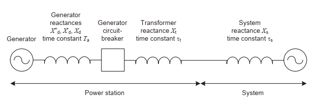
Figure 1 – Schematic of a Power Station Generator connected to a Grid
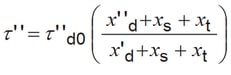
The out-of-phase current (Ioph) which will flow in the above circuit can be approximately calculated using the following equation when the generator is in a no-load situation prior to the out-of-phase condition.
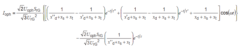
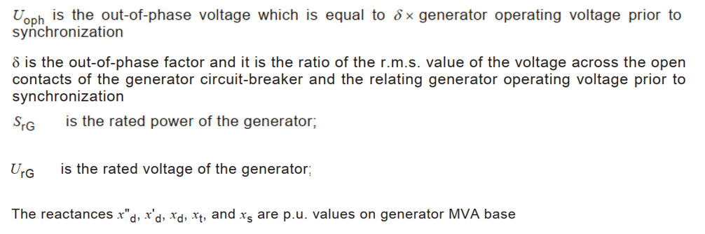
Where:
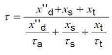
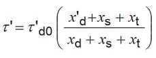
The time constant, transient time constant and sub-transient time constants are calculated as follows:
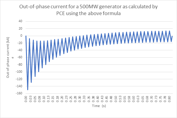
Applying the above formulae to a typical example of a 500MW generator yields the following OOP fault current:
Out of Phase Switching
Out-of-phase (OOP) switching conditions occur at a coupling of two network parts of equal operating voltages, the equivalent sources of which have different phase angles, partly or entirely 180◦ out of phase (refer to Fig 2 below). A difference in the phase-angle of the rotating vectors representing the source voltages causes out-of-phase currents across the connection which must be interrupted by a circuit-breaker. Somewhere along the connection the voltage vector will decrease to close to zero, and this location is called the equilibrium point.
Note that unlike terminal faults where usually an arc is present, this is not the case here. The out-of-phase current may be larger than the transient or even the sub-transient short-circuit current of a generator. The following diagram may be used to depict an out-of-phase fault. Fault currents can be calculated for a range of angles between voltages S1 and S2. Typically these calculations would include out-of-phase angles of 30o 60o 90o 180o.
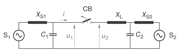
Figure 2 – Equivalent single-phase circuit of an out-of-phase fault
Transient Recovery Voltage
Transient recovery voltage (TRV) is the voltage which appears across the contacts of a circuit breaker after the contacts have opened. When a circuit breaker clears a fault, the circuit breaker must both stop the flow of fault current and also resist the subsequent TRV. If the TRV exceeds the capabilities of the circuit breaker, the current will restrike and the fault clearing process must be repeated.
In normal fault-switching duties, the load-side TRV component decays to zero. In the out-of-phase situation however, the load-side TRV component will decay to the power-frequency of the S2-source (see figure 3 below). As a result, OOP switching duty is characterized by a very high TRV peak with a moderate RRRV and a high current. The TRV of the out-of-phase test duty shows the highest peak value of all switching duties.
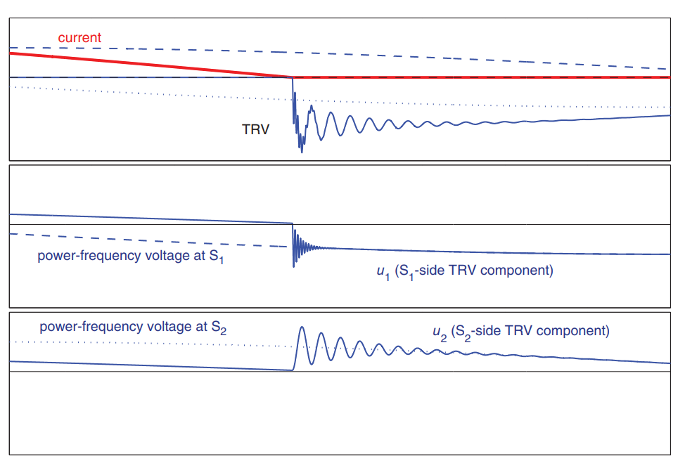
Figure 3 – Out-of-Phase TRV and its components. The dashed and dotted traces show the power-frequency voltages of source S1 and S2 respectively
In the above example, note that the TRV is made up of a power frequency component, and two natural frequency components. The total TRV is the sum of all of these and may exceed 3 x the system voltage.
Conclusion
This is a specialist subject for which PCE does not pretend to have all the answers. It is however a subject which is likely to be of interest to many power electrical engineers. While we are happy to share our learning on the subject, we would direct those with a particular interest to the references listed below.
References
- IEEE Std C37.013 – 1997 IEEE Standard for AC High-Voltage Generator Circuit Breakers Rated on a Symmetrical Current Basis
- IEC/IEEE 62271-37-013: 2015 Alternating Current Generator Circuit Breakers (Dual Logo Standard)
- Switching in Electrical Transmission and Distribution Systems: By René Smeets, Lou van der Sluis, Mirsad Kapetanovic, David F. Peelo, Anton Janssen
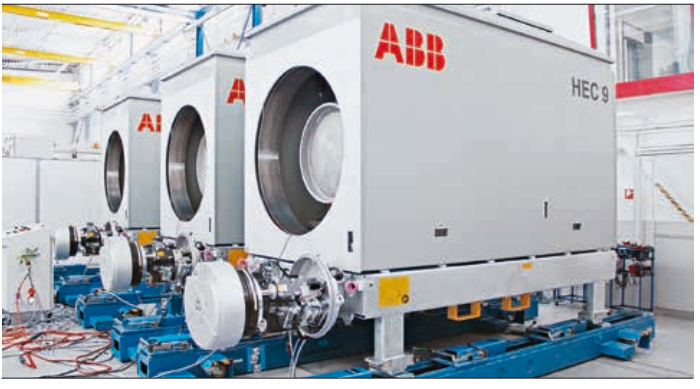
- ABB Review – Special Report High Voltage Products Photo: GCB type HEC 9 at a factory acceptance test
- Paper No. PCIC Europe EUR18_11 By Andreas Brandt ABB AG & Andrea Ferruccio ABB SPA - The IEC/ANSI Dual-Standard for Generator Circuit Breakers – Background characteristics and how it changes the game
- ABB Technical Application Paper No. 22 Medium voltage generator circuit-breakers by ABB SPA